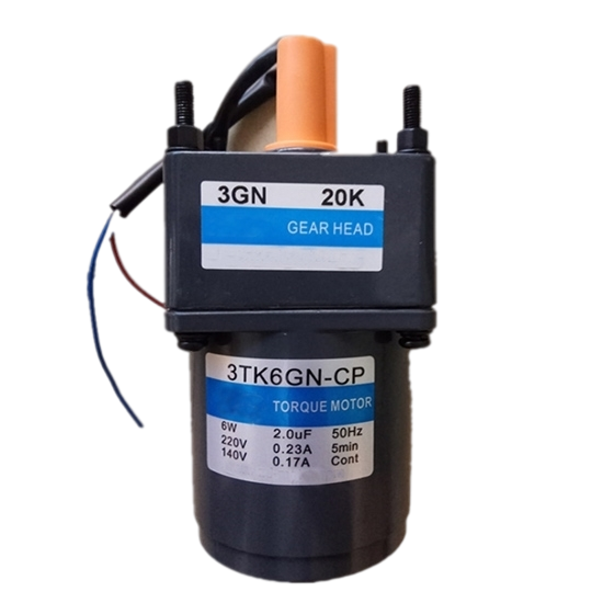
This article will introduce you to how to choose the torque of the reducer. The previous post has already introduced the tips for a geared motor. Before starting the preliminary design, the following factors must be known.
- The type, powers and speeds of the prime mover. The overall ratio of the gearbox.
- The types of unit required – parallel or angled drive.
- The application.
- Any abnormal operating conditions. The disposition of the input to output shaft.
- The direction of rotation of the shafts.
- Any outside loads that could influence the unit, e.g. overhung loads, brakes, outboard bearing etc.
- The type of couplings to be fitted.
- Any space restriction.
To obtain the basic size of the gearbox, the nominal torque at the output shaft is calculated, using the absorbed torque at the driven machine, or the prime mover torque multiplied by the gearbox ratio if the absorbed torque is unknown.
It may be possible to obtain a torque–time diagram of the drive, which will give a comprehensive result of the complete duty cycle. There are three important points to remember when calculating the nominal torque:

- That if a brake is positioned anywhere before the gearbox output shaft, the unit should be sized on the brake torque, (assuming this torque is greater than the motor torque). This is because any external loads back driving the gearbox will be sustained by the unit until the brake slips. The above is also true of any form of back stopping (anti-reversing) device. A check should also be made on the kinetic energy that would have to be sustained by the unit if the brake is to be applied in an emergency.
- That some prime movers, namely electric motors, can develop 2 or more times full load torque (FLT) on start up. If stop/start is a frequent occurrence then the gearbox must be sized accordingly.
- Those rigid type couplings can transmit shock more easily to the gearbox than can flexible or gear type couplings, and the application factor selected accordingly.
To select the basic size, the nominal torque must be multiplied by a service factor (see Table 2). These are based on field experience and take into account the working conditions for that particular application.
It should also be noted that some motors can run at varying powers and speeds. The maximum torque is used for rating the gears for power based on an equivalent life to suit the duty cycles, while the maximum speed is used to ascertain the pitch line velocities.
Most manufacturers of gearboxes produce excellent free catalogs from which can be gleaned a lot of useful information, including approximate size of units for a given power, thermal ratings, shaft sizes, calculations, etc.
The above figures are based on 10 hrs/day duty. For 3 hrs/day duty multiply above by 0.85. For 24 hrs/day duty, multiply above by 1.25.
NOTE – It is usual to equate a running time of 10 hrs/day to a total life of 22,000 hrs, and 24 hrs/day to 50,000 hrs.
Examples of driven machine classifications
- Uniform: Generators, Constant Density Mixer.
- Moderate Shock: Bucket Elevators, Concrete Mixers.
- Heavy Shock: Stone Crusher, Sugar Mill, Steel Mill Draw Bench.